Page 1 of 2 12 LastLast
Results 1 to 10 of 586

Thread: NSX Health Check Service

Hybrid View

Previous Post Previous Post   Next Post Next Post
  1. #1
    Join Date
    Sep 2008
    Location
    Bucks, UK
    Posts
    2,235
    Blog Entries
    2685

    Default

    Hi, Tim.
    The answer is simple.

    The parts list/diagram doesn't always show the actual shape/location of each parts for all Year models.

    As you experienced, there is only one diagram on the parts list for the two different shape/location of Main relays for DBW and non-DBW models.

    Presuming that you have RHD model and if you want to be sure, please have a look at under the bonnet or inside the engine bay.


    DBW model
    Click image for larger version. 

Name:	DBW01.JPG 
Views:	301 
Size:	190.8 KB 
ID:	7308 Click image for larger version. 

Name:	DBW02.JPG 
Views:	298 
Size:	167.3 KB 
ID:	7309
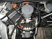
    You need Main Relay #39400-SL0-A01

    You will see LOOPED black cable surrounding the brake fluid reservoir and connected to the black plastic cube box inside the front compartment under the bonnet.

    Also, at the right side of the engine bay, you will see thick black hose with red text on it. This is the fuel line from the fuel filter.
    On DBW model, you WON'T see thick cable running in parallel to the fuel line like the one on non-DBW model below.


    non-DBW model
    Click image for larger version. 

Name:	NonDBW01.JPG 
Views:	272 
Size:	197.2 KB 
ID:	7310 Click image for larger version. 

Name:	NonDBW02.JPG 
Views:	294 
Size:	175.5 KB 
ID:	7311
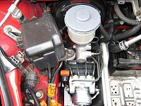
    You need Main Relay #39400-SL0-003

    There is no looped black cable surrounding the brake fluid reservoir but still, you will see black plastic cube box nearby so don't get confused.

    At the right side of the engine bay, you will see thick black hose with red text on it. This is the fuel line from the fuel filter.
    On non-DBW model, you WILL see thick cable running in parallel to the fuel line. This is the TH cable running all the way from the front to the TH body at the left side of the engine and hence, non-DriveByWire.

    I'm not a fan of Year model as sometimes, people get confused with registered year against Year model.
    You may have 97 registered NSX but not necessarily 97 Year model NSX.

    The best is to check against the VIN but if you check the above photos and 100% sure that your NSX is DBW, then your Main Relay is located around the right shoulder of your driver seat for RHD model.

    Wow, more than GBP109 for the Main Relay.....
    I'm quite sure if you ask Andy at vtecdirect, he would be able to source it much cheaper.
    I always keep one each in stock at my place for owners.
    Depending on the exchange rate and delivery charge from Japan/US, I would assume it would be about GBP50.00.

    Regards,
    Kaz
    Last edited by Kaz-kzukNA1; 22-07-2010 at 12:35 PM. Reason: Extra info

  2. #2
    Join Date
    Sep 2008
    Location
    Bucks, UK
    Posts
    2,235
    Blog Entries
    2685

    Default Timing Belt, Water Pump, Valve Clearance services #2

    Now back to the TB/WP service on the facelifted Silver NSX.

    Originally, we were planning to carry out the TB/WP service together with the Coolant system refurbishment before Japfest. However, I only managed to finish the Coolant system and Crank Pulley services in time due to my personal reason. Thus, some of the parts and Type-2 coolant were wasted by carrying out TB/WP service after the event but I covered these as it was my personal matter causing the changes in plan.

    Also, the owner had to drive his NSX all the way to my place again using his precious time and fuel. I offered the owner something but he was a very generous man and gently declined it so instead, I carried out the A/C CCU service and cleaning of A/C cabin temperature sensor for free. Once again, I always feel I’m very lucky to be able to work and meet these generous owners.

    So, the service started by talking to the owner.

    The owner told me that this would be the first TB/WP service on this NSX but the valve cover was removed by the main dealer in the past for valve clearance adjustment.
    So far, he didn’t feel any strange vibration at idling but still got some chattering noise even after the valve clearance was adjusted.

    Click image for larger version. 

Name:	Oil01.JPG 
Views:	304 
Size:	171.4 KB 
ID:	7314 Click image for larger version. 

Name:	Oil02.JPG 
Views:	289 
Size:	210.8 KB 
ID:	7315 Click image for larger version. 

Name:	Oil03.JPG 
Views:	285 
Size:	197.1 KB 
ID:	7316
    During the last service before Japfest, I noticed unusual amount of oil leakage for such a low mileage NSX so I was also interested to find the cause of this issue.

    Click image for larger version. 

Name:	Cleaned.JPG 
Views:	292 
Size:	169.8 KB 
ID:	7317 Click image for larger version. 

Name:	OilPanGasketLaterModel.JPG 
Views:	299 
Size:	183.5 KB 
ID:	7318
    The engine area was inspected again.
    Last time, I cleaned as much as possible the oil leakage and the oil pan area was quite clean even after the track session and long mileage driving so there was no need to replace the oil pan gasket.

    I already had the parts but it was not clear last time whether it was leaking from the oil pan gasket or not due to the excessive oil leakage from the upper area of the engine and leaking down to the oil pan.


  3. #3
    Join Date
    Sep 2008
    Location
    Bucks, UK
    Posts
    2,235
    Blog Entries
    2685

    Default

    Click image for larger version. 

Name:	SpoolValve.JPG 
Views:	291 
Size:	201.9 KB 
ID:	7319
    The spool valve and Oil Press sender unit area were clean apart from the usual leakage from camshaft black cap area so the filter at the spool valve and O-rings for the sender unit were not replaced.
    This NSX already got the latest design Lost Motion Assy so there was no need to replace them at this low mileage.

    I always carry out the compression check on the engine before opening the engine.

    This will provide me with some idea on the condition of the engine by comparing it to the data from lots of other engines measured in the past. NA1 and NA2 engines will show different range and tendency depending on the engine status and measuring conditions.

    Click image for larger version. 

Name:	DisableINJlaterModel.JPG 
Views:	271 
Size:	168.7 KB 
ID:	7321 Click image for larger version. 

Name:	Leave.JPG 
Views:	276 
Size:	114.7 KB 
ID:	7322 Click image for larger version. 

Name:	SparkPlugs.JPG 
Views:	284 
Size:	283.2 KB 
ID:	7320
    Removing the injector terminal block at the right side of the engine to disable the fuel injection during the compression check. On earlier models, you will have injector resistor unit instead.

    While preparing for the compression test, I noticed that there were lots of leaves around the intake chamber. Not sure how they managed to get in there but had to be cleaned before I can go any further. After cleaning them, the IGN Coils and Spark plugs were removed.

    In order to re-install them at the same location, they were marked with the cyl #.
    Click image for larger version. 

Name:	No1Coil.JPG 
Views:	287 
Size:	226.9 KB 
ID:	7323
    As seen on many other NSX, the IGN coil #1 (rear bank) was showing rust at the fixing tab due to the moisture getting inside. Another reason why it is best to replace IGN Coil cover seal at the time of TB service and regularly apply silicone grease until next service.

    The rust was smoothed out and silicon grease was applied to prevent future corrosion.
    Spark plugs looked fine and burnt in nice light brown colour at the insulator.

    One of them showed a little extra oil at the thread so probably not torqued to the spec when it was removed in the past. As it was still at very low mileage, they were not replaced at this point.


  4. #4
    Join Date
    Sep 2008
    Location
    Bucks, UK
    Posts
    2,235
    Blog Entries
    2685

    Default

    Click image for larger version. 

Name:	PrepCompCheck.JPG 
Views:	258 
Size:	188.8 KB 
ID:	7324
    Air filter box was removed, TH pedal was kept to the floor and the compression was measured. The absolute value is just a reference and although they were fine, the deviation was slightly larger than expected. Later, I found that the valve clearance was out of spec on some of the cyl even they were adjusted in the past.

    Click image for larger version. 

Name:	HeadCoverBefore.JPG 
Views:	275 
Size:	175.9 KB 
ID:	7325
    The valve/head cover was removed.
    The route of blow-by gas was changed on the later NA1 and NA2 engines.
    As it was still at low mileage and the engine oil was replaced regularly, the backside of the valve cover was quite clean even without the usage of oil catch tank.

    Click image for larger version. 

Name:	HeadCoverPrep01.JPG 
Views:	257 
Size:	161.4 KB 
ID:	7329 Click image for larger version. 

Name:	HeadCoverPrep02.JPG 
Views:	268 
Size:	168.0 KB 
ID:	7330
    Remove the old gasket and seals.
    Clean the head cover at this stage and let it dry.
    Then, install the new cover gasket and plug hole seals using small amount of liquid gasket. This will allow well enough time for the liquid gasket to set before re-installing it back on the engine. Keep them in a clean place.

    Click image for larger version. 

Name:	HeadCoverSealCaught.JPG 
Views:	259 
Size:	159.2 KB 
ID:	7331
    Now I understood why there was so much oil leakage for such a new car. When the valve/head cover was re-installed after the valve clearance adjustment last time, the cover gasket was kinked and got caught between the cover and the engine head. Thus, it was not possible to achieve good seal. Surprisingly, it was the same for both Fornt and Rear cover and thus, the oil was leaking from both Front and Rear exhaust port side.

  5. #5
    Join Date
    Sep 2008
    Location
    Bucks, UK
    Posts
    2,235
    Blog Entries
    2685

    Default

    No wonder why I had to spend many hours cleaning the engine.

    Click image for larger version. 

Name:	PartiallyClean01.JPG 
Views:	256 
Size:	136.6 KB 
ID:	7332 Click image for larger version. 

Name:	PartiallyClean02.JPG 
Views:	249 
Size:	150.1 KB 
ID:	7333
    At the end, I think it was quicker to just take out the engine to clean the outside of engine thoroughly because even I spent many hours, I couldn’t get my hands behind the exhaust header flange as well as some of the area below the camshaft black cap. Another reason for why the NSX specialists in Japan take out the engine even just for the TB service.

    As I don’t have access to engine clean room yet, all the doors and windows had to be closed. Even in UK, at that time, it was so hot and humid that I felt like working in the garage at Malaysia GP.

    Click image for larger version. 

Name:	Residue01.JPG 
Views:	261 
Size:	142.3 KB 
ID:	7334
    Looks like the person who carried out the valve clearance adjustment didn’t clean the residue of liquid gasket. Looks like the white one is the Honda bond from the factory and the black one was used last time.

    Click image for larger version. 

Name:	Prep02.JPG 
Views:	256 
Size:	210.5 KB 
ID:	7335Click image for larger version. 

Name:	TDC1.JPG 
Views:	258 
Size:	147.0 KB 
ID:	7336
    Align the white marker on the crank pulley to the twin arrows on the TB lower cover to set #1 cyl at TDC.


  6. #6
    Join Date
    Sep 2008
    Location
    Bucks, UK
    Posts
    2,235
    Blog Entries
    2685

    Default

    Click image for larger version. 

Name:	TBcoverBolt.JPG 
Views:	253 
Size:	175.2 KB 
ID:	7337
    Start removing the bolts from the TB lower and mid rear/front covers. As expected, some of the bolts were heavily corroded and had to be replaced with the new one.

    Click image for larger version. 

Name:	Seal01.JPG 
Views:	253 
Size:	156.7 KB 
ID:	7338 Click image for larger version. 

Name:	Seal02.JPG 
Views:	243 
Size:	152.4 KB 
ID:	7339
    Click image for larger version. 

Name:	Seal03.JPG 
Views:	254 
Size:	154.8 KB 
ID:	7340 Click image for larger version. 

Name:	TBcover.JPG 
Views:	248 
Size:	180.8 KB 
ID:	7341
    As mentioned above, the oil was leaking from both the front and rear head covers at the exhaust port side.
    Because of this, the rubber seals at the front, rear and lower covers were all wet but they did a great job on protecting the TB.

    Unlike my old Prelude, there was no trace of oil at all on the TB.

    These seals are going to be replaced with the new ones.

  7. #7
    Join Date
    Sep 2008
    Location
    Bucks, UK
    Posts
    2,235
    Blog Entries
    2685

    Default

    As we don’t know the history of the engine, it is important to first check the current alignment of the TB against the marking on the Cam gears and TB cover plate.
    This engine was fine and it looked like the TB was never removed since it left the factory.

    Click image for larger version. 

Name:	TBmarking.JPG 
Views:	247 
Size:	177.4 KB 
ID:	7342
    In order to get some reference when installing the new TB, it is good idea to put some markings on the existing belt and transferring them to the new one. These are reference only and you must check the timing by carefully looking at the line on the TB cover plate and the cam gears.

    Click image for larger version. 

Name:	WP01.JPG 
Views:	306 
Size:	201.0 KB 
ID:	7343 Click image for larger version. 

Name:	WP02.JPG 
Views:	290 
Size:	167.3 KB 
ID:	7344 Click image for larger version. 

Name:	WP03.JPG 
Views:	278 
Size:	179.0 KB 
ID:	7345
    WP removed. The shop towel at the right is covering the hole for the Oil level dip stick. Make sure to cover it before removing the WP as you may spill some coolant.

    The new and old WP. Although it was at very low mileage, the old WP was already showing rust on the impeller.

    Another reason for why it would be best to replace the WP at the time of TB service regardless of the mileage.
    I don't want to rely on this rusty WP for many years until the next TB service....
    Quite often, people will only inspect the bearing by rotating the WP without removing it and thus, no chance to check the impeller side.

    Special bolts used for the WP. You can re-use them by cleaning the old seal/lock and applying liquid gasket like Honda bond. I just use new ones as it is quicker and possibly cheaper considering the amount of time required to prepare the old ones. Remember to clean the thread hole on the engine side as well although the space is very limited.

    Click image for larger version. 

Name:	LeakTest.JPG 
Views:	281 
Size:	103.4 KB 
ID:	7346
    Once the new WP installed, make sure to carry out vacuum or pressure test on the coolant system before going any further. You don’t want to find any issues on the coolant system after you put everything back in place only to disassemble again.

    More to follow.....

  8. #8
    Join Date
    Dec 2007
    Location
    Switzerland
    Posts
    1,006

    Default

    Good work, Kaz!

    One note, I've seen that the spark plugs were treated with anti-size in the past which looks like copperpaste. I do not favor it. I use hightemp ceramicpaste which is electrically neutral.

  9. #9
    Join Date
    Sep 2008
    Location
    Bucks, UK
    Posts
    2,235
    Blog Entries
    2685

    Default

    Quote Originally Posted by goldnsx View Post
    Good work, Kaz!

    One note, I've seen that the spark plugs were treated with anti-size in the past which looks like copperpaste. I do not favor it. I use hightemp ceramicpaste which is electrically neutral.
    Hi, goldnsx.

    There were no copper grease used on the thread of the spark plugs when I removed them. It just the colour effect of digital camera, I guess.

    As long as you don't accidentaly touch the insulator area of the spark plug or the IGN Coil with the conductive material, I don't see any issues using copper grease on the spark plugs. I know F1 engine mechanics from different manufactures using it with extreme care.
    You need good GND between the spark plug and engine block.

    I think O2 sensor manufacture prefers to use ceramicpaste.

    Kaz

  10. #10

    Default

    Quote Originally Posted by Kaz-kzukNA1 View Post
    In order to re-install them at the same location, they were marked with the cyl
    Kaz I always do the same, but very interested to hear your points in why the front and rear banks are marked as RR and FR when they look the same? I know the front coil packs installed are connector side down, on the rear they are installed connector side up, but still wonder why they are marked as RR and FR as I cannot see any difference?
    Last edited by Sudesh; 23-07-2010 at 08:25 PM.
    “Once you eliminate the impossible, whatever remains, no matter how improbable, must be the truth.”

    後は、残っているものに関係なく、不可能なことを排除する方法 ありそうもない、真実でなければなりません。

Page 1 of 2 12 LastLast

Posting Permissions

  • You may not post new threads
  • You may not post replies
  • You may not post attachments
  • You may not edit your posts
  •