Results 1 to 10 of 26

Thread: Ecu reset procedure.....

Hybrid View

Previous Post Previous Post   Next Post Next Post
  1. #1
    Join Date
    Sep 2005
    Location
    Garden of England
    Posts
    2,778

    Default

    alas, just to be a pain, the idle is not so bad, but the gearbox computer dropped under its 'the TPS is ok and i can work with it' threshold.... the signal being erratic once more, with the traction control computer connected or not.....

    so i connected a wire to the 5v reference supply that feeds all the sensors...... and hooked that up to the oscilloscope too!

    with gearbox and TCS computers disconnected.... i switched on, the yellow line being the 5v ref supply, the blue being the tps output....


    5v supply solid as a rock, but safe to say there's something up there with the blue line then! even before it's started, and not touching the throttle, it's all over the place.....

    this was the tps i swapped on to the car when the gearbox computer was having it's tps issues..... so swap it back then.... ho hum

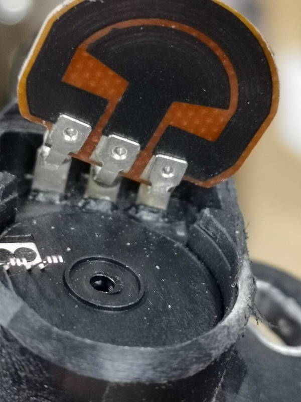
    on the bench i tested it, it's a basic potentiometer 0v, 5v, and the voltage output depending on where the wiper is, a simple resistor arrangement....

    so on the bench, end to end resistance 4.8k ohms, ok acceptable, one side to wiper 1.6k, the other side to wiper 6.8k... hmmm something definitely not right there, it means the first reading should have been more like 8.5k, AND the value is changing with the heat of my hand holding it! no wonder that was causing issues!

    i'm guessing when i found the signal stabilized after disconnecting the TCS computer, it dropped the load on the tps so it was happier, but them decided it wasn't... or it was just coincidence?? i hate intermittent faults! grrr

    IMG_20190427_142548 by jon sutherland, on Flickr

    new idle screw, pcv valve in and i still couldn't get the idle down to spec , so new fast idle valve and ECAV fitted....

    IMG_20190427_145728 by jon sutherland, on Flickr

    IMG_20190427_145703 by jon sutherland, on Flickr

    now i can stall the car on the idle screw! some progress at least!

    with the original TPS in place and it seems happy, output levels where they should be, and the idle is at the correct levels too.... now it's a waiting game to see if the gearbox computer finds it's TPS levels too low..... again.......
    aka Jonathan!!

    '92 charlotte green auto.... as a daily
    '37 Ford Y street rod......... something for the weekend!

    ...... if a photobucket pic is foggy, click it, and it'll take you to the clear version, yes, it's a clicking faff....

  2. #2
    Join Date
    Sep 2005
    Location
    Garden of England
    Posts
    2,778

    Default

    of course, why would honda dream of using a conventional style variable resistor, when they can make it overly complicated....

    2019-04-28_12-12-05 by jon sutherland, on Flickr

    normally the centre connection is a metal track, and a wiper on the carbon resistor element, giving a simple resistance value (a percentage of the overall resistance)

    a toiny pic.....

    Click image for larger version. 

Name:	Variable-Resistor-Terminals.jpg 
Views:	202 
Size:	34.8 KB 
ID:	13690

    the honda style has 2 carbon tracks, just to be awkward...
    aka Jonathan!!

    '92 charlotte green auto.... as a daily
    '37 Ford Y street rod......... something for the weekend!

    ...... if a photobucket pic is foggy, click it, and it'll take you to the clear version, yes, it's a clicking faff....

  3. #3
    Join Date
    Jan 2018
    Location
    Near Stuttgart, Germany
    Posts
    255
    Blog Entries
    25

    Default

    Would say that's not an unusual design, given that the inner track has zero resistance: https://cdn.instructables.com/F2R/0K...97Q2.LARGE.jpg :-)
    1997 JDM Custom Order AT VIN 1400005 - Stock
    Heineken's Garage

  4. #4
    Join Date
    Sep 2005
    Location
    Garden of England
    Posts
    2,778

    Default

    It has a resistance of approx 1.5k ohms... So quite unusual!!!! That linked one has a metal centre ring, the TPS one is carbon.....
    aka Jonathan!!

    '92 charlotte green auto.... as a daily
    '37 Ford Y street rod......... something for the weekend!

    ...... if a photobucket pic is foggy, click it, and it'll take you to the clear version, yes, it's a clicking faff....

  5. #5
    Join Date
    Jan 2018
    Location
    Near Stuttgart, Germany
    Posts
    255
    Blog Entries
    25

    Default

    Ooops, that's indeed unusual
    May I ask how the resulting resistance curve looks like?
    1997 JDM Custom Order AT VIN 1400005 - Stock
    Heineken's Garage

  6. #6
    Join Date
    Sep 2005
    Location
    Garden of England
    Posts
    2,778

    Default

    Like a 1k5 resistor on the centre wiper, min 1k5, max 6k8 or there abouts... But the test is all voltage based, 0.5v to 4.5v-ish, but the TPS has a mechanical offset when it's mounted so that would account for the required bottom end offset anyway!

    On a more positive note the car is back to pretty much how it was originally, but with a different TCS ECU..... And everything is behaving .... At the moment....
    Last edited by britlude; 28-04-2019 at 01:49 PM.
    aka Jonathan!!

    '92 charlotte green auto.... as a daily
    '37 Ford Y street rod......... something for the weekend!

    ...... if a photobucket pic is foggy, click it, and it'll take you to the clear version, yes, it's a clicking faff....

  7. #7
    Join Date
    Sep 2005
    Location
    Garden of England
    Posts
    2,778

    Default

    Update.... Just to be awkward the issue wasn't resolved as I hoped it would be, everything was pretty much returned to how it was with the exception of the TCS computer and the additional wiring I had added to bypass the TPS sensor loom......

    Then though a series of unfortunate events and a technical cockup on my part, I managed to kill my engine ECU.... Spiked 12v into the 5v rail, which tends to upset the chips in the computers..... subsequently having no fuel pump control I had to source another..... after purchasing a replacement and crossing my fingers, the engine is running again......

    The oscilloscope was still hooked up and the TPS signal was a lot cleaner, far less noise spikes....


    As a precaution I also swapped in spare AT controller and TCS units, just in case the spiked 5v rail had affected them, and it seems to be running better than ever, and with an idle where it should have been all the time....

    So was it the main ECU all along???? Time will tell...
    Last edited by britlude; 15-05-2019 at 07:44 AM.
    aka Jonathan!!

    '92 charlotte green auto.... as a daily
    '37 Ford Y street rod......... something for the weekend!

    ...... if a photobucket pic is foggy, click it, and it'll take you to the clear version, yes, it's a clicking faff....

Posting Permissions

  • You may not post new threads
  • You may not post replies
  • You may not post attachments
  • You may not edit your posts
  •