
Not yet, it's on my list of things to do today. I've been studying the Workshop Manual this morning & making a list of things to do & making sure I don't accidentally fry an ECU !Originally Posted by goldnsx


 Platinum Member

Not yet, it's on my list of things to do today. I've been studying the Workshop Manual this morning & making a list of things to do & making sure I don't accidentally fry an ECU !
Wix
Platinum Member
It would be my first test. I once heard of an A/C stator failure.
Just undo the connector next to the oil stick and apply 12 V to the A/C coil at the compressor and see if it spins. If not you'll need a new stator/clutch unit for the compressor.
Platinum Member
Done this check applied 12V to the compressor & compressor clutch engages, so all would seem good with the compressor.
Still working through the other checks but already seeing some strange results. I have got 12V at the harness end of the compressor red wire intermittently. I thought it was due to the fact I had a jumper wire across the 2 terminals of the Triple Pressure Switch and when I reconnected it to the switch the 12V at the red wire went to 0V. Having repeated the test again with the jumper wire across the Press Switch, I now can't see 12V at the harness end of the compressor red wire..........
Currently checking relays & fuses again but all seems good still, so I'm beginning to suspect either the Cooling fan ECU or the PGM ECU but if one of the temperature sensors is faulty (ambient, interior), maybe they could cause one of the ECU's to switch off the 12V to the compressor......
Wix
Platinum Member
Having spent nearly all of the day, going through a lot of the procedures in the Workshop Manual numerous times, I can get the Compressor to activate intermittently. I think the issue is with the Cooling Fan ECU as I can occasionally get the Compressor to activate by wiggling its connector. I can try the same thing again & it won't activate the Compressor. The only other thing I've found, is the Ambient Air Temp sensor is out of range of the specified Resistance levels.
Reading this post by Kaz,
http://www.nsxcb.co.uk/entry.php?981...n-Control-Unit
it gives me more confidence in my conclusion.
Wix
Platinum Member
Do you mean the one in the bumper face?
Not sure where the A/C system gets get the info from exactly but the A/C is shot off at very low temps.
 Platinum Member
Have you ever noticed the rad fan start operating immediately after turning IGSW in P2 ON position even when the engine is cold?
Both R&L condenser fans and the eng bay fan (if you have one) could be triggered at the same time.
As your issue is intermittent and if not done yet, best re-soldering all of the joints inside the FCU (Fan Control Unit).
Quite a lot to re-solder but still DIY level.
The condenser fans and the compressor CL are controlled separately so even when the former spinning, the latter may not engage.
Inputs to the FCU:
Thermo sensor (mounted on the thermostat cover, different from the temperature sender unit for the temperature gauge or the TW sensor for the ECU)
CCU A/C request
Tripple Press Hi-Lo switch
Output from the FCU:
Rad fan Lo relay control (Low speed mode)
Rad fan Hi relay control (High speed mode, bypass the resistor block)
Eng bay fan relay control (if you have one)
R&L condenser fan relay control
ACS (A/C Switch) signal to ECU
A/C CCU:
Evaporator temperature sensor input
A/C On/Off request to FCU
ECU:
ACC (A/C Clutch) output signal controlling the A/C compressor CL relay.
This is how the A/C compressor CL is controlled.
1. At the CCU, if the Evaporator temperature is above 4degC AND manually or automatically the A/C On is requested, the CCU sends the A/C On request to the FCU.
2. If the Thermo sensor is below 130degC AND the Triple Press Hi-Lo switch is On, the FCU sends ACS request to ECU.
The all of the fans (Rad, R&L condenser, Eng bay ones) are controlled by the Thermo sensor and the A/C On/Off request from the CCU but without the Tripple Press Hi-Lo switch status.
Therefore, if the coolant is extremely hot like above 130degC OR the Tripple Press Hi-Lo switch detects abnormal refrigerant pressure (too high or too low), there is a situation where the CCU is requesting to engage the A/C compressor and while the condenser fans are spinning, the compressor CL won't engage as the FCU doesn't enable the ACS request to the ECU.
3. ECU receives the ACS request from the FCU and enables the A/C compressor CL relay through ACC signal.
At the same time, adjust the engine control based on ACS and Tripple Press MID switch status.
So, multiple controllers and sensors involved.
The outside temperature sensor at the front bumper is not used for the compressor CL control.
If disconnected, the CCU will just use 10degC as the failsafe data and carries on with the rest of the control.
You can force the CCU into the evaporator temperature control mode and send out A/C On request to FCU using the following method.
a. There is no need to start the engine. Just set IGSW into P2 ON position.
b. Press [ AUTO ] dial to power up the CCU if switched off at the last driving cycle.
c. Not required but to save the battery, set fan speed at MIN (1 click from auto mode).
d. Either press on the [ A/C ] switch on the CCU and get [ A/C ON ] on the display or turn the temperature dial all the way counter-clockwise to set it at 18degC.
This will force the CCU into evaporator temperature control mode.
If the evapo sensor is above 4degC, it will send out A/C On request signal to the FCU.
Kaz
Last edited by Kaz-kzukNA1; 18-04-2021 at 05:36 PM. Reason: typo
Platinum Member
Thanks for this Kaz, it's answering some of the questions I have with regards the way the ECU's interact with each other, to control the cooling/A-C system. This info should help me determine what the problem is.
These are my answers to your questions.
1. Yes, both condenser fans can come on when the the engine is cold. Sometimes the first morning start of the day. This doesn't occur every time though.
2. I had the FCU re-soldered 2 years ago, after the main radiator fan not switching on & the temperature gauge creeping up a little too high for comfort. This repair did/has seemed to work for the radiator fan.
I've ordered a new FCU & Ambient Temp sensor from Amayama, which will either solve the problem or at least eliminate these two components.
I'll keep this post updated as and when I do more work on the car, when the parts arrive from Japan.
Cheers.
Wix
Platinum Member
Minor update, checked the continuity of the wire (BLU/BLK) between the FCU & PGM-ECU & it's ok, no breakages.
Also took the FCU apart to look at the circuit board. I can't see any dry joints or leakage from any of the components but I guess the only definitive check is to replace the FCU.
Wix
 Platinum Member
One potential option is to re-flow all solder points - sometimes these cracks are thin as a hair and hard to detect visually.
1997 JDM Custom Order AT VIN 1400005 - Stock
Heineken's Garage
Platinum Member
You really need re-soldering all of the joints.
From your photo and what you mentioned, looks like you only re-soldered very limited number of joints in the past.
As Heineken mentioned above, you are looking for the hair line crack.

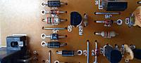
This is one example.
As you already opened the FCU, you will know how far this photo was enlarged compared to the actual size of the soldering pad.
Arrows show some of the cracked joints.
In fact almost all of the joints in this photo are cracked.
Almost all of your photo are out of focus and not high enough resolution so hard to tell but even so, there are many suspicious joints.
This is from your 4th photo.
Circled ones very likely to be cracked, arrows are suspicious but hard to tell.
Kaz
 Posting Permissions

 Reply With Quote