


Today at Atelier Kaz - ex-Honda R&D, F1, Indy/CART engineer
ABS Upgrade Preparation
by , 02-12-2012 at 03:21 PM (5026 Views)
Ill be upgrading the ABS to the latest spec for one owner in
new year and Im writing this in preparation for it.
His NSX is heavily modified in all sorts of areas including the
engine and brake so would like the owner to check the space
under the bonnet so that there wont be any surprise when I
start working on his NSX.
After talking to the owner and found out that
he uses his NSX on track and also the way he brakes into the corner,
I even considered offering the ABS upgrade using the
NSX-R software and the NSX-R brake booster but with unknown
weight distribution of his heavily modified NSX and also
using aftermarket brake caliper which will result in different
brake balance compared to NSX-R,
decided to go for the standard ABS setup.
In fact, lots of Japanese owners with upgraded ABS together with
big caliper setup are happily improving their lap time using
the standard ABS software so I would rather use the proven setup.
First, in order to remove the existing ABS and then install the new one,
please check that there is no aftermarket solid pipe work etc, in
the green arrow section.
If you are using racing spec radiator with extra thick core or
any additional devices in the green arrow section,
please let me know in advance.
Also, if you have something sitting/above the spare wheel holder plate
(flat silver square object in the right half of the photo),
please let me know as I must move it first before removing the battery.
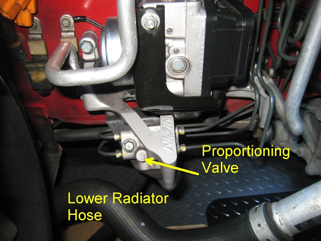
This area should be clear if you still have your existing ABS unit but
I must have enough space under the ABS modulator bracket in order to
install the new brake pipes connected to the new proportioning valve that
is part of the ABS upgrade.
Again, if you have special lower radiator hose or extra devices behind
the radiator, please let me know.
In Japan, I know some of the owners tracking their NSX are
installing extra devices in this area.
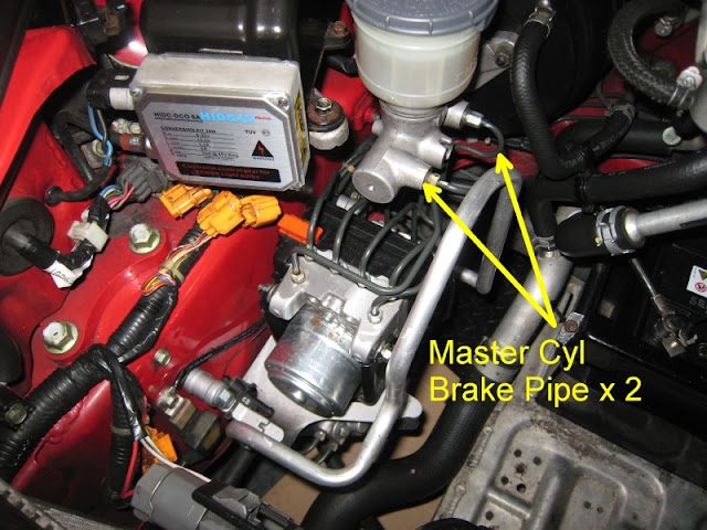
8 x brake pipes will be replaced with new ones including the
two pipes from the brake master cyl.
If you have any aftermarket parts such as brake master cyl stiffener, etc,
please let me know.
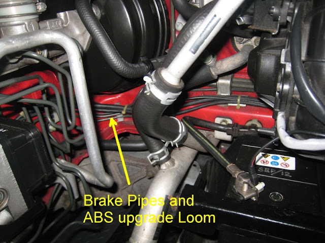
I need to have access behind the ABS modulator below the brake booster pack
(the round black housing).
This is where the new brake pipes as well as the ABS upgrade loom are
going to be routed.
I must take your battery out of the bay and then remove the
blower motor fan.
These are required to route the new brake pipes and ABS upgrade loom.
If you have something like security hone, etc, that may obstruct the
process, please let me know.
By looking into the front compartment, you will see
black plastic vertical drain duct next to the blower motor fan.
Behind there, you will see 6 way metal block that connects the
brake and clutch pipes.
I must have access to this.
And if you have modified the front brake pipes especially the end fitting for
any reasons, please let me know.
Hope I have covered everything so that I can simulate the service work with
potential extra work in my head.
Regards,
Kaz


Tags:
abs,
abs upgrade

- Categories
- ABS Upgrade
 Email Blog Entry


