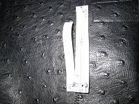
10. Now we need to create something to establish the connection to the contact plate at the base of boss.
For this, I used the cardboard from the cereal box to use it as a template.
(I think our member Sudesh used great idea to create this circuit and he posted it on Prime in the past.)
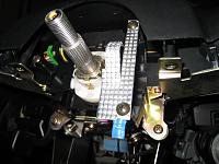
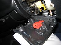
Based on the cardboard template, I cut out the aluminium sheet and placed it like this. I used the two fixing screws originally designed to hold the cable reel.
Make sure that this hand made part doesnt touch any of the metal part other than the contact plate at the boss. Otherwise, your horn will be continuously triggered when you re-connect the battery.
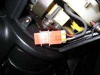
Route the long cable that was placed at pin #1 of the yellow connector above and connect the ring terminal to the hand made metal sheet with the screw as in the photo.
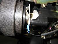
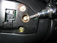
11. Apply good quality grease at the contact plate of the boss. This is very important as after several years, it will start to make some noise every time when you turn the steering wheel if the grease got dried out. For this reason, I didnt use the ordinary conductive copper grease. Instead, I used race spec bearing grease. Its not conductive so dont apply too much.
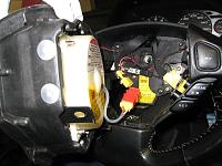
12. Regarding the tension of arch shaped metal sheet, you just need to play with it. Not too soft but not too hard against the contact plate. It will look like this when the boss was placed in place.
...
...
...


 Reply With Quote