-
16-12-2010, 11:31 PM
#541

While the server was down, I couldnt update this thread as well as dealing with the PM. Although all of the owners were happy to be updated through this site, I may need to start looking into setting up my own blog in order to be able to update the owners on a timely manner. Also, I prefer using email than PM as it is much easier to manage so many communications every day.
As Im bit behind the schedule, couldnt take lots of photos.
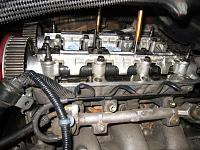
Rear bank camshaft, cam holders, pulleys installed.
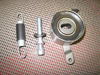
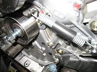
New TB tensioner, spring and bolt. Tensioner installed.
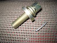
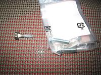
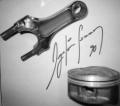
The owner bought a new crank pulley bolt and the key so these will be replaced on this NSX.
-
16-12-2010, 11:42 PM
#542
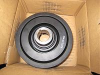
New crank pulley. Quite often, this is not replaced during the standard TB service but for me, this is a MUST item to be replaced.
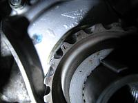
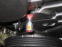
Setting the crank shaft at #1 TDC by aligning the pointer on the TB drive pulley and the marker on the Oil pump.
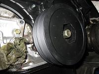
TB installed and to check the accuracy of the pointer on the TB lower cover, the cover and the crank pulley were installed temporarily.
As found on other early model NSX, there was tiny-tiny difference between the marker on the lower cover against the white mark on the crank pulley.
By the way, the accuracy of some of the OEM parts are getting worse.
For example, these were known issues on some of the MT parts, latest ABS modulator and so on. Also, some of the electronics modules are discontinued for the early models so you need to rely on people who can repair them than replacing them.
Removed the lower cover and crank pulley and in the process of one of the most important process, the tensioning of TB.
During the last TB service, it seems that the TB was not tensioned properly and thus, it was loose when I checked before start of the service.
Next is the Valve Clearance adjustment. Another very important stage and for me, the most time consuming process.
More to follow.
Kaz
-
18-12-2010, 10:25 PM
#543
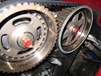
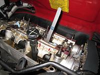
Before adjusting the tension of TB, just check again and again and again the alignment of four camshafts and the crank shaft.
In Japan, some of the NSX are running with wrong timing especially at the rear bank due to most of the places carrying out the TB service without taking the engine out.
Easy to make mistake on the alignment as well as lack of TB tension will result in jump of tooth when the car suddenly span off at the track or if sudden reverse torque was applied while the clutch was engaged such as engine stall at the steep up-hill.
Almost all of the reputable NSX specialist in Japan will be taking the engine out during TB/WP service as the owners tend to ask extra service at the same time.
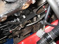
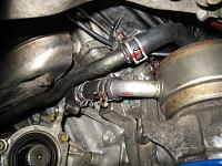
After adjusting the TB tension, installed the TB lower cover together with the Oil level dip stick tube and A/C idle pulley.
-
18-12-2010, 10:29 PM
#544
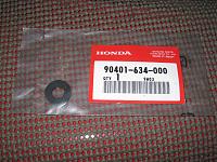
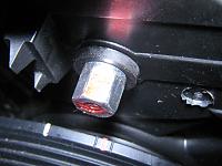
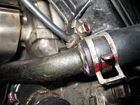
On many UK based NSX, I noticed that the O-ring/seal at the TB tension adjuster bolt was missing. This is the seal and the part no is 90401-634-000.
Without the seal, there is a gap between the bolt and lower cover.
Once the seal is installed, it will prevent any moisture/debris getting inside of TB lower cover which may damage the TB in longer term.
Adjusting the valve clearance. Although I use the same tool each time, I prefer to adjust the actual feeling of the gauge by touching the metal of the engine to check the temperature. As it is very cold these days, a touch of difference will be applied. It is less than 0.01mm but still you can feel the difference.
Double checked the torque and the clearance on the Front bank and moving onto the Rear bank but I had to stop here for other project.
I was hoping to start the engine by now so looks like Ill be working over the weekend
More to follow.
Kaz
-
21-12-2010, 12:54 PM
#545
Rear bank valve clearance and lock nut torque double checked.
Start putting back everything in place.
As I always replace all of the rubber seals on the TB Lower, Front and Rear covers, they are very tight fit and always struggle to align the bolt holes.
In fact, on this NSX, I had to re-thread some of the bolt holes as a few bolts were not the original ones and also they were screwed in with wrong angle. I had to replace one of the bolt as I couldnt achieve the specified torque.
If you are doing this DIY, one tip for you. Use your 5mm pin punch that you used for locking the camshafts at the Front bank to align the mid covers.
The length and the diameter is perfect to align the bolt holes on the TB Front and Rear mid covers and reduces significant time in installing these.
-
21-12-2010, 01:01 PM
#546
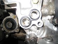
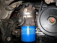
The new figure of 8 O-ring installed for Oil Cooler base and used Honda bond on two of the bolts for securing the Cooler base.
These two coolant hoses are now permanently installed and secured.
Fit the old oil filter for the time being in preparation for fire up of the engine.
-
21-12-2010, 01:03 PM
#547
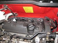
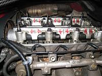
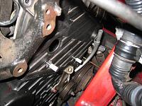
Cleaned the four corners of the Valve covers and the mating surface before applying liquid gasket.
Front and Rear Valve covers are torqued down.
-
21-12-2010, 01:08 PM
#548
Spark plugs thread cleaned and applied small amount of copper grease before installation.
Small amount of silicone grease was applied on the IGN coil metal base.
These need to come off again after the first fire up for another compression check.
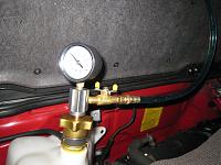
Vacuum test the cooling system again while connecting the O2 sensors, connectors and so on.
Oil Press Warning sensor cable re-routed properly and secured to the sensor.
And, fill up the system with Honda Type 2 Blue coolant.
For C30A engine, you can drain about 14L of coolant before disconnecting any hoses/pipes.
After flushing the system, disconnecting the hoses, thermostat, WP, etc and pushing out any remaining water with compressed air, the system is nearly empty.
By using the vacuum fill method, you can put just below 16L of coolant into the system and then another about 0.5L while adjusting the coolant level. C32B engine is slightly less than this.
Once happy with the state of liquid gasket and the oil level, fired up the engine for a few minutes, quick initial check around the car, warm up the engine and cool it down over night to adjust the coolant level.
Next, the compression check and the drive shaft.
I want to wash the car but the rain water is frozen so I need to use the tap water.
I dont know when I can carry out the test driving session as the local roads are still covered in snow...
More to follow...
Kaz
-
21-12-2010, 05:01 PM
#549

Originally Posted by
Kaz-kzukNA1

Excellent work!
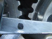
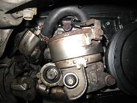
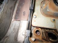
Just wondering: it this corrosion, the brown area?
-
22-12-2010, 12:27 AM
#550
Hi, goldnsx.
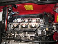
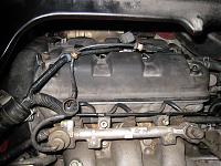
The brown areas are the mixture of corrosion and the colour of blowby gas deposit after cleaning it.
On early C30A engine, the fresh air is introduced to the Rear valve cover and the blowby gas is forwarded to the Front valve cover and then passed onto the TH body through the check valve.
Because of this, on this model, the valve cover, cam shaft holders & cap at the front side tend to show more brown colour than the rear ones. The colour and area size depend on how the engine was used, how the car was driven and how often the engine oil was replaced.
Quite often, people say no need to replace engine oil if you dont drive the car regularly because of low mileage.
Also, some people tends to just start the engine occasionally and let it idle for a while without moving the car to circulate the engine oil during storage period.
Personally, I think these are not ideal from blowby gas point of view.
When the engine is cold, the metal clearance is still not at operating condition resulting in lots of blowby gas with moisture and etc.
Because of this, if the car was used for frequent short distance trips or the engine oil was not replaced regularly, it will show wider and darker brown area.
The later C30A and also all of the C32B engines are using the reversed routing for the blowby gas compared to early C30A engine so the brown area will tend to show up more at the rear bank.
If you track the car regularly or if you don't want to loose the lap time because of blowby gas, it is better to install oil catch tank or something to prevent oil mist into the intake.
 Posting Permissions
- You may not post new threads
- You may not post replies
- You may not post attachments
- You may not edit your posts
-
Forum Rules


 Reply With Quote