-
06-12-2010, 10:26 PM
#531

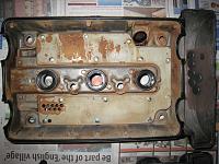
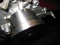
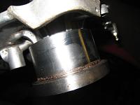
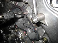
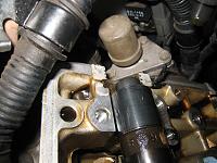
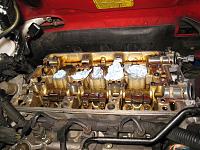
As seen on many NSX and also in the previous post, IGN Coils at the rear bank were corroded/rusted due to moisture passing through the IGN coil cover gasket.
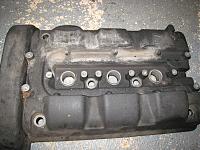
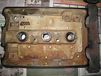
As you can see, there was clear marking on the rear bank valve cover that the moisture stayed there for long period.
This will happen on any NSX if the rear bank IGN coil cover gasket was not replaced or if it was not massaged with silicone grease at a certain interval.
Even just washing the car will cause the same problem if the gasket was already tired.
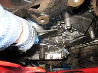
Without taking the engine out, you need to be very careful on re-assembly or installation of most of the parts during TB service.
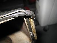
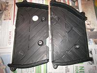
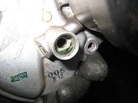
On this NSX, the Front Valve Cover gasket was dislocated during the re-assembly and being cut resulting in oil leakage around the engine block as well as allowing some of the oil into the inside of TB Mid and Lower cover.
Addition to this, in UK, quite often the WP is not replaced during TB service and the lower cover was being re-used. On this NSX, the expensive rubber seal was missing from the TB Lower cover. Glad that we decided to carry out the TB service this time before its too late.
-
06-12-2010, 10:41 PM
#532
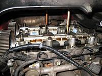
Spent extra time cleaning the engine.
Some of the before and after photos. Cleaned as much as possible.
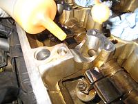
After removing the mid covers and before going any further, I normally install the new seals/gaskets with small amount of liquid gasket to cure it in time for the re-assembly.
-
06-12-2010, 10:44 PM
#533
So, new seals on the Front/Rear mid TB, Lower TB, Valve and IGN coil covers were installed.
Dont ask me where these were done
. I promise that I kept the carpet clean.
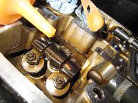
Backed off the valve clearance adjuster in preparation for removing the four camshafts.
In the process of replacing the WP.
More to follow.
Kaz
Last edited by Kaz-kzukNA1; 06-12-2010 at 10:55 PM.
Reason: Failed cut and paste
-
08-12-2010, 09:11 PM
#534
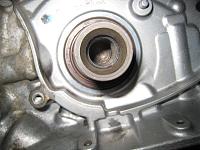
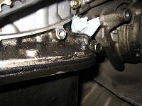
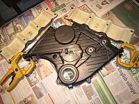
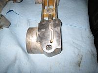
The oil seal at the Crank shaft/Oil pump was very clean and no sign of leakage so it is going to be re-used.
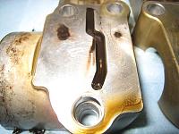
As mentioned previously, the WP was never replaced during the TB service on this NSX. It was still using the old original design.
The position of coolant seepage hole was changed on the later design.
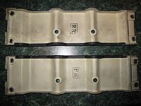
The old design on the left and the new one on the right. The TB Lower cover is also different because of this seepage hole position.
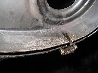
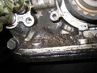
As the entire seal rubber was missing from the Lower cover, the WP driven pulley was somewhat rusty and some dirt managed to get inside the TB area.
-
08-12-2010, 09:15 PM
#535
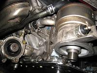
Over the years, it is quite normal to see small amount of coolant seepage.
WP, Lower cover and seal rubber are going to be replaced with new ones during this service.
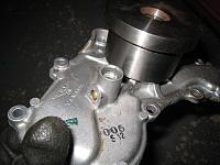
Scrape off any corrosion from the mating surface of WP.
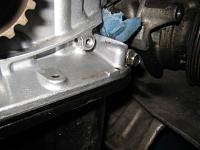
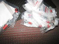
In the process of removing the old red sealant which is pre-applied to all of the WP bolts.
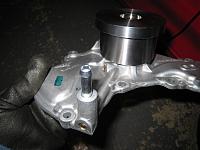
New OEM WP bolts with red sealant.
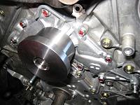
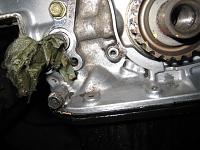
New WP installed and torqued to the spec.
-
08-12-2010, 09:23 PM
#536
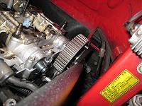
Temporarily, re-installed the Oil cooler base with remaining two cooling system hoses to carry out the leak check.
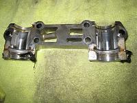
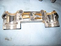
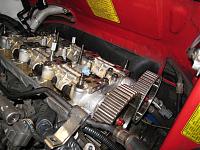
While testing the cooling system, started removing the camshafts holders, covers and camshafts.
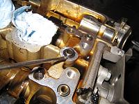
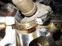
O-ring at the dowel pin under the #1 cam holder has to be replaced with a new one.
Looks like during the previous TB service, the original liquid gasket (white one) was not cleaned before applying the new one (black one). Another reason why I saw many engine oil seepage from the valve cover and camshaft black cap area.
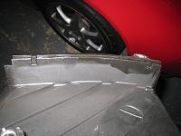
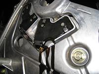
As seen on all of the NSX, the black compound of CKP/CYL sensor was melting and running down the back plate.
-
08-12-2010, 09:27 PM
#537
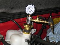
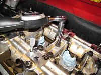
Left the leak tester for more than 20min and not a single movement of the needle so I'm happy with the cooling system.
Both Camshafts from Front bank are removed and being cleaned. Engine block ready for another cleaning session.
Rear bank to follow.
I better start cleaning the house as my boss is coming back and I still have lots of parts inside the house.
More to follow.
Kaz
-
12-12-2010, 01:01 PM
#538
Been busy with other projects so couldnt spend much time on this NSX recently but now Im back.
As seen on many NSX, the cable for one of the Oil pressure sensor was trapped in the past. It could easily trigger the low oil pressure warning light but the owner didnt mention anything so probably the internal wire was fine.
If you take your NSX to the normal garage or main dealer, during standard TB/WP/Valve adjust service, your camshaft wont be removed.
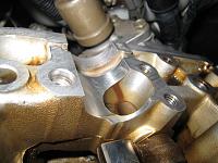
However, there are tiny-tiny oil jets and passages on the cam holders and over the years, it will accumulate the sticky debris from the blowby and so on.
The dirty oil passage on one of the cam holder and this can be seen on almost all of the engines. You are relying on these oil passage and jets for the lubrication of camshaft and so on. Another reason to remove the camshafts and thoroughly clean the passage at the time of TB service.
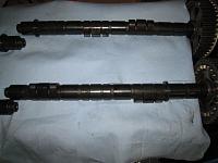
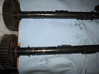
Front Bank and Rear bank camshafts cleaned and inspected for abnormal wear.
-
12-12-2010, 01:10 PM
#539
It seems that the black liquid gasket that was used during the last TB service was applied without the surface being degreased. It came off by just wiping off with my fingers.
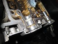
Before and after cleaning the old liquid gaskets.
-
12-12-2010, 01:14 PM
#540
Applying Eng oil before installing the camshaft. Also, applying the oil to the rocker arms.
Double checking the toque of camshaft pulley bolt.
Carefully tightening the cam holder bolts in sequence using the small digital torque wrench.
Front bank done.
On some of NSX engines, the 5mm parallel pin punch won’t fit into the hole at the Front exhaust camshaft and the holder cover [Edit: when] it was set at #1 TDC. This engine was the same so had to move the cam just a tiny amount to insert the pin. We don’t use this hole/pin for the timing alignment and just using it to lock the cam to prevent any movement so not a problem.
Moving onto rear bank.
More to follow.
Kaz
Last edited by Kaz-kzukNA1; 12-12-2010 at 01:19 PM.
Reason: Added [Edit:] section
 Posting Permissions
- You may not post new threads
- You may not post replies
- You may not post attachments
- You may not edit your posts
-
Forum Rules


 Reply With Quote