Page 50 of 58 FirstFirst ... 404849505152 ... LastLast
Results 491 to 500 of 580

Thread: NSX Health Check Service

  1. #491
    Join Date
    Sep 2008
    Location
    Bucks, UK
    Posts
    2,234
    Blog Entries
    2685

    Default

    Have been away from this site for awhile but now I'm back.


    While looking at the engine bay, I noticed lots of leaves inside the V-bank and surrounding area. So, decided to clear them out first.

    Click image for larger version. 

Name:	FromEngineBay.JPG 
Views:	245 
Size:	263.3 KB 
ID:	7868
    This is not all of them but still, quite a lot. For some reason, this is not the first time I saw this amount of leaves inside the engine bay. Possibly something to do with the air flow caused by the wind inside the engine bay while you park, where you park and with the engine cover on…

    Click image for larger version. 

Name:	LooksLikeOilFilter.JPG 
Views:	260 
Size:	171.7 KB 
ID:	7869
    Looks like the oil filter ….
    I knew it would be tight with so much corrosion on the case and it already lost its original shape. Worried that I may not be able to apply enough torque before the attachment starts to slip… Challenge continues….

    Click image for larger version. 

Name:	O2SensorRearStrangeFixing.JPG 
Views:	251 
Size:	113.9 KB 
ID:	7870 Click image for larger version. 

Name:	MissingBolt.JPG 
Views:	258 
Size:	209.0 KB 
ID:	7871 Click image for larger version. 

Name:	OilPressSensorCableNotHeld.JPG 
Views:	261 
Size:	210.1 KB 
ID:	7873
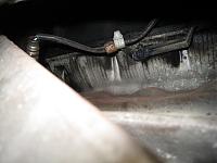
    In the process of removing the right drive shaft.

    I found that the Rear O2 sensor was replaced with aftermarket one but the cable was not long enough. It was using some sort of fixing to hold the cable to the bracket but the connector was not secured at the original position.


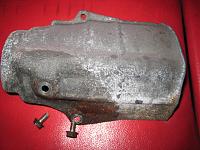
    The heatshield covering the inner joint of right drive shaft was missing one of the three fixing bolts. It was not seared off but just missing…

    The cable for the oil pressure sensor was not held in place. Not the first time to see this....

  2. #492
    Join Date
    Sep 2008
    Location
    Bucks, UK
    Posts
    2,234
    Blog Entries
    2685

    Default

    Click image for larger version. 

Name:	SeizedSpline.JPG 
Views:	253 
Size:	160.7 KB 
ID:	7874
    The spline was really seized into the hub. Even with the hydraulic puller, I had to leave it overnight. Eventually, it came out slowly.

    Click image for larger version. 

Name:	RHdriveshaft.JPG 
Views:	235 
Size:	228.4 KB 
ID:	7875 Click image for larger version. 

Name:	CorrodedTriggerTeeth.JPG 
Views:	247 
Size:	208.5 KB 
ID:	7876 Click image for larger version. 

Name:	WhichOneDoYouWant.JPG 
Views:	272 
Size:	179.9 KB 
ID:	7877
    The right drive shaft.

    Initially, I thought the lots and lots of debris on the trigger teeth were contaminated grease from the outer joint.
    However, when closely inspected, it was actually the trigger teeth got corroded and lost their original sharp shape.

    We were very lucky that I already started rebuilding the right drive shaft using my spares as it is not cost effective to restore these 10’s of trigger teeth one by one using micro file.
    Comparison of the good and bad trigger teeth in the photo. The refurbished outer joint painted in black with high temperature spec paint.

    Also, there is no guarantee that the rollers inside this outer joint are not damaged after seeing so much grease splashed everywhere.

  3. #493
    Join Date
    Sep 2008
    Location
    Bucks, UK
    Posts
    2,234
    Blog Entries
    2685

    Default

    Click image for larger version. 

Name:	GreaseEverywhere01.JPG 
Views:	270 
Size:	176.5 KB 
ID:	7878 Click image for larger version. 

Name:	GreaseEverywhere02.JPG 
Views:	247 
Size:	212.5 KB 
ID:	7879
    Spending hours cleaning these sticky nasty grease….. Already used more than 1L of cleaning agent…

    Click image for larger version. 

Name:	RRwheelSpeedSensor01.JPG 
Views:	250 
Size:	206.6 KB 
ID:	7880 Click image for larger version. 

Name:	RRwheelSpeedSensor02.JPG 
Views:	237 
Size:	142.1 KB 
ID:	7881
    Due to the corrosion at the trigger teeth, the sensor head was scraped and pushed back a little.
    It was not enough to kill the sensor and because the sensor was still working, it didn’t trigger any error at ABS or TCS.

    However, because of the increased gap, the signal level got weaken at lower speed. I think the combination of wider gap at the sensor head and badly corroded trigger teeth caused the high frequency brake pedal kick back every time when the car was just about to stop.


    Click image for larger version. 

Name:	NewSensorHead.JPG 
Views:	236 
Size:	118.6 KB 
ID:	7882
    The new sensor head looks like this.
    From the past experience and the report from another owner, I knew I’m going to struggle to take the sensor head out of the hub.

    At the end, I had to destroy the sensor head as the corrosion was all around the sensor housing and fatten it. When the sensor is new, the housing is in black as above photo. However, when it came off, it was covered in white corrosion dust.


    My biggest concern now is the left side drive shaft. The trigger teeth is in the same condition as the right side and I presume the sensor head is also damaged by now.

    Unfortunately, I don’t have spare MT left drive shaft nor the spare RL speed sensor. I may not be able to fix the brake pedal kick back issue without working on the left side so I think we need to work on this next time…
    Last edited by Kaz-kzukNA1; 07-11-2010 at 01:42 PM. Reason: English....

  4. #494
    Join Date
    Sep 2008
    Location
    Bucks, UK
    Posts
    2,234
    Blog Entries
    2685

    Default

    Click image for larger version. 

Name:	AbsAccum.JPG 
Views:	240 
Size:	177.8 KB 
ID:	7883 Click image for larger version. 

Name:	AbsAccumHose.JPG 
Views:	259 
Size:	183.3 KB 
ID:	7884 Click image for larger version. 

Name:	AbsPumpBracket.JPG 
Views:	245 
Size:	181.4 KB 
ID:	7885

    The ABS accumulator.

    As the member britlude reported, I thought about replacing the accumulator and pressure switch Assy from US as I think it is part of the ABS multiple issues.

    However, after looking at the state of the ABS, I decided it is not cost effective to invest into this old/tired system.

    There is no guarantee that it won’t fail in a few years time. Considering the state of the brake pipes and other ABS parts, we are now discussing about investing into the latest one body ABS module instead.

  5. #495
    Join Date
    Sep 2008
    Location
    Bucks, UK
    Posts
    2,234
    Blog Entries
    2685

    Default

    Click image for larger version. 

Name:	InnerPadSeizedBracket.JPG 
Views:	238 
Size:	191.3 KB 
ID:	7888 Click image for larger version. 

Name:	GreaseDriedUpSliderPins.JPG 
Views:	232 
Size:	146.6 KB 
ID:	7887
    Disassembling the brake calliper.

    The inner pad on both Front callipers was seized inside the calliper bracket. I had to hammer them out to take them off.

    This will result in very solid pedal feeling yet the car won’t slow down efficiently. Quite lot of owners are getting used to this feeling and won’t notice the lack of stopping power.


    All four callipers were not seized but the slider mechanism was very heavy on all of them. When checked the state of the grease at the slider pins, it was almost dried up and not like a grease. In fact, when I wiped it off, it came off in block shape….

    Another reason why it is so important to have your brake system refurbished at regular interval.

    Click image for larger version. 

Name:	BanjoBoltNotReUsable.JPG 
Views:	243 
Size:	89.8 KB 
ID:	7886
    I don’t think I can re-use this banjo bolt….

    Click image for larger version. 

Name:	RearBrakeHoseBracket.JPG 
Views:	244 
Size:	200.4 KB 
ID:	7889
    Nicely corroded bolts at the rear brake hose bracket.

    More to follow…

  6. #496
    Join Date
    Dec 2007
    Location
    Switzerland
    Posts
    1,006

    Default

    Wow, that's a nightmare of an amount of rust.

  7. #497
    Join Date
    Apr 2004
    Location
    West Sussex
    Posts
    4,537

    Default

    Quote Originally Posted by Kaz-kzukNA1 View Post
    Click image for larger version. 

Name:	FrontRearTBcoverGasket.JPG 
Views:	305 
Size:	181.9 KB 
ID:	7649 Click image for larger version. 

Name:	LowerTBcoverGasket.JPG 
Views:	324 
Size:	187.7 KB 
ID:	7651 Click image for larger version. 

Name:	HeadCoverGasket.JPG 
Views:	328 
Size:	180.4 KB 
ID:	7650
    Apart from the IGN Coil Cover gasket, most of the gaskets will be installed into the covers at this stage to allow the liquid gasket to cure.

    The two rubber seals each on the Front and Rear TB cover.
    The very expensive single gasket on the TB Lower cover.
    Two different gaskets and three round IGN Coil hole seals at the head/valve cover.
    Hi Kaz,
    Which liquid gasket do you use or recommend? Hondabond?
    Is this the correct part number for the gasket set - 12030-PR7-010?
    Last edited by NSXGB; 08-11-2010 at 09:53 PM.

  8. #498
    Join Date
    Sep 2008
    Location
    Bucks, UK
    Posts
    2,234
    Blog Entries
    2685

    Default

    Hi, NSXGB.

    In UK, I don’t have enough experience to recommend alternative products so Honda bond would be my first choice.

    In Japan, I always use the specific one from one of the chemical company. In fact, I always keep them in stock at my place and brought them with me to UK.
    As same as the grease that I use, this is part of my know-how so I would like to keep it for the people using my services.

    Regarding the gaskets, there are lots of them replaced during the TB service.
    Please refer to post #345 for the parts list. If you haven't changed the default 'view' setup for the NSXCB site, then it is on Page 35.

    I think you are referring to the one used at the head/valve cover and if that is the case, then your number is correct. Please note that you need two for servicing both head/valve covers.


    Regards,
    Kaz

  9. #499

    Default

    All lovely Kaz but when are you going to offer the clutch service? Enquiring minds want to know LOL!

  10. #500
    Join Date
    Sep 2008
    Location
    Bucks, UK
    Posts
    2,234
    Blog Entries
    2685

    Default

    All four callipers are now removed.

    Click image for larger version. 

Name:	Front01.JPG 
Views:	260 
Size:	252.3 KB 
ID:	7890 Click image for larger version. 

Name:	Front02.JPG 
Views:	238 
Size:	265.2 KB 
ID:	7891 Click image for larger version. 

Name:	Front03.JPG 
Views:	236 
Size:	232.8 KB 
ID:	7892
    As I don’t want any debris to get inside while I’m installing the pistons, boots, seals, etc, all of them need to be cleaned and washed thoroughly. It’s going to take a while….

    Click image for larger version. 

Name:	Bleeder.JPG 
Views:	244 
Size:	192.0 KB 
ID:	7893
    Looks like a bleeder screw… Completely corroded…

Page 50 of 58 FirstFirst ... 404849505152 ... LastLast

Posting Permissions

  • You may not post new threads
  • You may not post replies
  • You may not post attachments
  • You may not edit your posts
  •