-
02-10-2010, 10:23 AM
#441

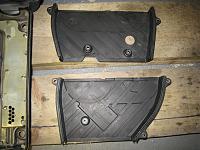
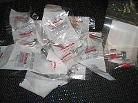
Apart from the IGN Coil Cover gasket, most of the gaskets will be installed into the covers at this stage to allow the liquid gasket to cure.
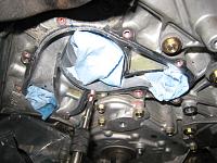
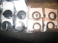
The two rubber seals each on the Front and Rear TB cover.
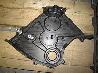
The very expensive single gasket on the TB Lower cover.
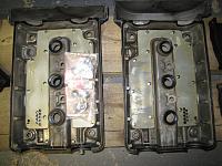
Two different gaskets and three round IGN Coil hole seals at the head/valve cover.
-
02-10-2010, 10:25 AM
#442
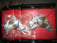
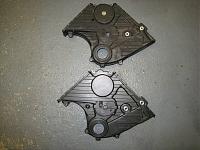
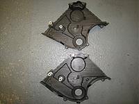
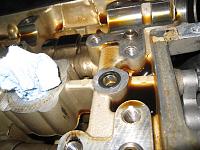
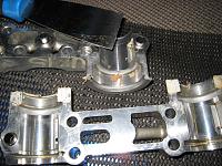
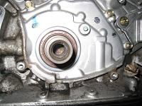
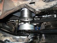
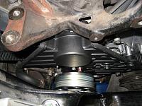
As expected, the water pump was never replaced in the past. It was still the original design and hence, the TB Lower cover was also the old design. Note the difference in the location of seeping hole at the lower cover as well as on the WP.
-
02-10-2010, 10:28 AM
#443
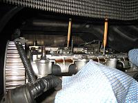
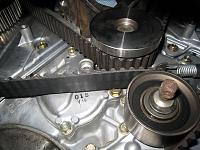
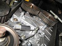
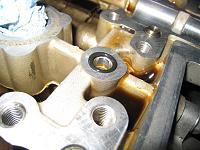
After removing the TB, it is very unlikely to happen but to be 100% sure not to move the camshaft accidentally while the crankshaft at #1 TDC, always lock the four camshaft with parallel pin punch or similar tool.
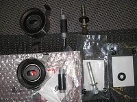
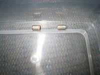
The water pump bearing showed small amount of rattle even for a short mileage so good to be replaced this time. Also, the TB tension adjuster bearing was showing tiny rattle.
Always replace this with the tension spring as well.
NSX doesnt have auto tension mechanism and once you set it at the time of TB service, you are relying on it until the next service. The spring will be used as a part of tension adjust process so it is best to use new one.
More to follow.
-
03-10-2010, 08:26 PM
#444
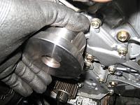
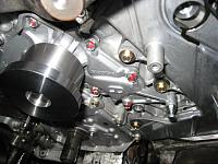
Bit difficult to see in the photo but cleaning the red sealant residue at the WP bolt thread. Use good quality tap to remove as much sealant as possible but with great care.
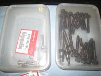
The two dowel pins for the WP and the new OEM WP bolts with red sealant.
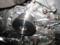
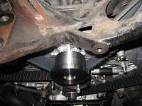
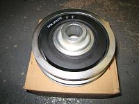
New latest WP installed and torque checked.
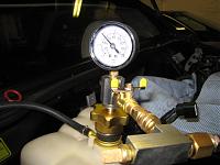
In order to double check the WP O-ring, carry out pressure/vacuum test on the coolant system again at this stage. You dont want to find any WP related issues after you have finished the TB service.
-
03-10-2010, 08:36 PM
#445
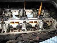
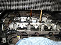
While keeping the coolant system under pressure/vacuum for leakage test, prepare for the camshaft removal.
Removing Front camshafts. There were some black residue at the oil passage of Front cam holder #2 & #3. Possibly the blow by and another reason for the importance of regular engine oil change especially if you drive NSX for a short distance regularly.
-
03-10-2010, 08:40 PM
#446
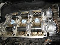
Dont forget to replace the O-ring at the Oil Passage under the cam holder #1. There is one O-ring at each bank.
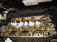
Both Front and Rear camshafts are now removed.
Time to clean the engine again to remove any liquid gasket residue around #1 and #4 cam holders.
More to follow.
-
07-10-2010, 09:38 PM
#447
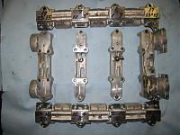
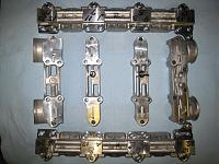
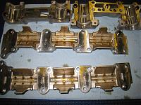
Scrape off the old gasket thoroughly.
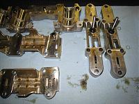
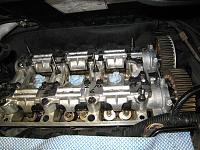
Front and Rear bank camshaft holders cleaned and inspected.
It is important to double check the tiny oil jet free from any debris.
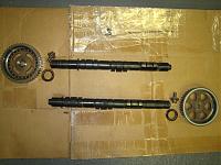
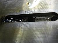
Cleaning the camshaft.
While the camshafts are off the car, this is the last chance to clean the back plate and the rest of the area.
-
07-10-2010, 09:43 PM
#448
Cleaning the area around oil pump and crank shaft oil seal.
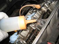
Prepare the cam seal and cap for the installation of camshaft.
Its not the soy sauce. Its the engine oil
New O-ring installed at No.1 cam holder on each bank.
In the process of installing the Front Camshaft.
-
07-10-2010, 09:51 PM
#449
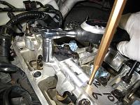
Applying torque to the bolts in the specific order in several turns using the digital torque wrench.
Very improtant process as this will affect the valve clearance adjustment later.
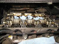
Front camshaft installed.
Rear camshaft installed.
TB installed.
Now, one of the most important process. The tensioning of TB.
There are several methods to carry this out but I prefer briefly installing the crank pulley and then lock it while applying force to four camshaft pulleys in specific order.
-
07-10-2010, 10:17 PM
#450
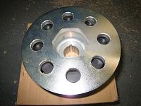
This NSX is AT so the crank pulley is different from the one for MT.
Final stage of adjusting the tension of TB by rotating the crank pulley until the blue mark meets the pointer on the TB Lower cover.
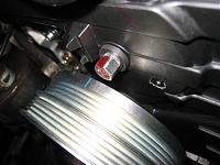
Torque the TB adjuster bolt to the spec and before you forget, install the O-ring/rubber seal over the TB tension adjuster bolt.
Quite often, I found this O-ring/rubber seal missing on UK based NSX.
The owner mentioned that he was experiecing some oil drip on the garage floor.
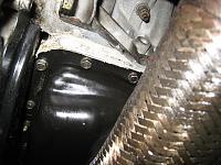
After cleaning the engine, I found some sealant used at one part of the oil pan area.
Normally, the oil leakage is from the oil pan gasket or from the head/valve cover area.
Looks like the person who worked on the oil pan gasket followed the specified torque figure on the Workshop manual.
That is way too much and one of the biggest reason for causing oil leakage.
Probably, it already de-formed the oil pan and requires replacement.
It requires removing the Front downpipe to remove the oil pan.
As I don't like removing it without having access to the spare O2 sensors, we will need to monitor whether the oil leakage was from the oil pan or from the head/valve cover area and select the appropriate measure next time.
Now it's time to take break before carrying out the valve clearance adjustment. Very delicate touch requried if you are carrying out this proess while the engine is on the car.
More to follow.
 Posting Permissions
- You may not post new threads
- You may not post replies
- You may not post attachments
- You may not edit your posts
-
Forum Rules


 Reply With Quote