Page 38 of 58 FirstFirst ... 28363738394048 ... LastLast
Results 371 to 380 of 580

Thread: NSX Health Check Service

  1. #371
    Join Date
    Sep 2008
    Location
    Bucks, UK
    Posts
    2,232
    Blog Entries
    2685

    Default

    Click image for larger version. 

Name:	TBdrivePulleyMark.JPG 
Views:	281 
Size:	120.6 KB 
ID:	7348
    By the way, on the TB drive pulley and oil pump, there is a TDC marking on them so make sure to keep them in this position and never move it while the crank and camshaft/valve are not at the right timng.

    Click image for larger version. 

Name:	CamRemoved.JPG 
Views:	282 
Size:	204.5 KB 
ID:	7350 Click image for larger version. 

Name:	DwelPinOring.JPG 
Views:	277 
Size:	193.3 KB 
ID:	7349
    Click image for larger version. 

Name:	CamHolderPlate.JPG 
Views:	277 
Size:	212.4 KB 
ID:	7351 Click image for larger version. 

Name:	Cleaning.JPG 
Views:	296 
Size:	132.0 KB 
ID:	7353
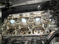
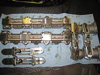
    Time to remove the camshaft.

    Loosen the bolts on the cam holder plates in sequence. I normally just write down the sequence number on the plate.

    Don’t forget to replace this O-ring at each bank on the dowel pin.

    This is very important as you are relying on this O-ring to keep enough oil pressure through the oil passage on the cam holder and holder plate. There are tiny holes on them to spray the oil to the camshaft and the rocker arms.

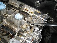
    Remove any liquid gasket residue and
    clean all parts before re-assembly. Again, it is important to blow compressed air on the tiny holes on each parts in order to establish clean oil passage.

  2. #372
    Join Date
    Sep 2008
    Location
    Bucks, UK
    Posts
    2,232
    Blog Entries
    2685

    Default

    Click image for larger version. 

Name:	TDCmarkTBplate.JPG 
Views:	276 
Size:	161.8 KB 
ID:	7354 Click image for larger version. 

Name:	TBlowerCover.JPG 
Views:	262 
Size:	179.2 KB 
ID:	7355 Click image for larger version. 

Name:	WPspringTensioner.JPG 
Views:	257 
Size:	159.5 KB 
ID:	7356
    The TDC marking on the TB cover plate. You need to use the mirror if the engine was not taken out from the chassis.

    Install the camshaft, cap and seals.

    The new TB lower cover and new rubber packing.


    New water pump, TB tensioner and spring installed.
    Install the TB and set it to proper tension.


    Check the timing, again, and again, and again.

    Click image for larger version. 

Name:	ValveAdj.JPG 
Views:	269 
Size:	160.6 KB 
ID:	7357
    Once you are done, it’s time for the valve clearance adjustment.
    You don’t want to compromise here.

    If you feel tired, just take some rest and come back later.


    In my philosophy, even you have exactly the same engine parts and tools, each engine will sound (and even perform) differently depending on who assembled/tuned the engine.

    It’s the delicate touch which makes the minute difference and each engine/chassis should be treated as an art than just a mechanical parts.


    I normally spend 3 – 4 hours just for the valve clearance adjustment.
    It can be done in about 2 hours but I prefer taking time especially for this process.

    You will be rewarded when you measure the compression after the service.

    Time well spent and the mechanical noise will be reduced if all 24 of them adjusted carefully.

  3. #373
    Join Date
    Sep 2008
    Location
    Bucks, UK
    Posts
    2,232
    Blog Entries
    2685

    Default

    Click image for larger version. 

Name:	FrontAdjusted.JPG 
Views:	262 
Size:	212.2 KB 
ID:	7359 Click image for larger version. 

Name:	RearAdjusted.JPG 
Views:	264 
Size:	194.2 KB 
ID:	7360 Click image for larger version. 

Name:	DoubleCheck.JPG 
Views:	259 
Size:	153.5 KB 
ID:	7358
    Front and Rear bank valve clearance adjusted.

    Before putting back the TB covers, make sure there is no oil/dirt on both side of the TB.

    Before putting back the TB cover, once again, double check the timing and the tension.
    I have seen many engines with 1 tooth off on the timing setup or very loose TB tension.

    Click image for larger version. 

Name:	MidFrontRearCoverSeals.JPG 
Views:	236 
Size:	163.9 KB 
ID:	7361 Click image for larger version. 

Name:	OilLevelGuage.JPG 
Views:	264 
Size:	281.0 KB 
ID:	7362
    New seals for the mid Front and Rear cover.
    New O-ring for the base of Oil Level gauge tube.


  4. #374
    Join Date
    Sep 2008
    Location
    Bucks, UK
    Posts
    2,232
    Blog Entries
    2685

    Default

    Click image for larger version. 

Name:	Coolant.JPG 
Views:	233 
Size:	161.7 KB 
ID:	7363 Click image for larger version. 

Name:	CompTest.JPG 
Views:	250 
Size:	201.5 KB 
ID:	7364
    Refill the coolant and time for another compression check.

    This time, the deviation between the cylinders should be smaller if you carefully adjusted the valve clearance.


    Click image for larger version. 

Name:	IgnCoilCoverSeal.JPG 
Views:	242 
Size:	159.2 KB 
ID:	7365 Click image for larger version. 

Name:	Sticker.JPG 
Views:	271 
Size:	135.5 KB 
ID:	7366
    Before installing the new IGN Coil cover seal, apply small amount of silicone grease.

    Here comes the special stickers included in the Japanese TB kit.
    The mileage and the date the service was carried out will be written on it and covered by the clear sticker.
    Then, it will be placed at the door opening sill. If you don’t like it, you can remove it but the owner liked it and happy to keep it there.

    Click image for larger version. 

Name:	Done.JPG 
Views:	270 
Size:	202.8 KB 
ID:	7367
    Done.

    I didn't have time to take photo for each step so this post won't show you all of the procedures but you can find it on many NSX related site includiing NSX Prime.

    Some of the sequences/photos may not be in the correct orders and as always, I didn't write down any know-hows in the post as the owners who visited my place paid for them but at least, I hope you can get some idea on the level of my services.

    After the service, the owner took his NSX for a long-long trip and very happy with the reduced noise, rpm pick up and nice fresh feelings.


    Time to prepare myself and my NSX for the Silverstone Classic...

    Regards,
    Kaz

  5. #375

    Default

    Quote Originally Posted by Kaz-kzukNA1 View Post
    ... as always, I didn't write down any know-hows in the post as the owners who visited my place paid for them but at least, I hope you can get some idea on the level of my services.
    Thank you for the knowledge you do share. The pictures you take and the know-how you provide are very valuable given that it is becoming ever more difficult to find real NSX specialists to take care of our cars. The NSX-trained mechanic at my local Honda dealership left the company years ago and there is no one left in my area who was trained to work on an NSX. Because of that, the knowledge you share is instrumental in keeping my NSX from entering a process of slow decline. And of course, if you would be willing to try your hand at adjusting cam gears, I would gladly drive the 1600 km each direction to bring my NSX to you.

  6. #376
    Join Date
    Sep 2008
    Location
    Bucks, UK
    Posts
    2,232
    Blog Entries
    2685

    Default

    Quote Originally Posted by Sudesh View Post
    Kaz I always do the same, but very interested to hear your points in why the front and rear banks are marked as RR and FR when they look the same? I know the front coil packs installed are connector side down, on the rear they are installed connector side up, but still wonder why they are marked as RR and FR as I cannot see any difference?
    Hi, Sudesh.

    I don’t know the reason why they are marked as RR and FR even they look the same…

    I have never tried it before but I heard the parts are the same between RR and FR and thus, they are interchangeable.

    Electronically, they should be the same and from outside, they look exactly the same so I guess, it is interchangeable.

    I didn’t even bother about the marking as I always put them back in their original position together with the spark plug.
    This will help me in the future if I have misfire or any engine related issues to diagnosis the problem.

    If I start putting them back in a different position, I’ll loose all of my precious history regarding what is happening inside the engine.

    When I have more time, I guess I can ask my friends back in Japan about the meaning of the RR and FR marking.

    Kaz

  7. #377
    Join Date
    Sep 2008
    Location
    Bucks, UK
    Posts
    2,232
    Blog Entries
    2685

    Default

    Quote Originally Posted by goldnsx View Post
    Good work, Kaz!

    One note, I've seen that the spark plugs were treated with anti-size in the past which looks like copperpaste. I do not favor it. I use hightemp ceramicpaste which is electrically neutral.
    Hi, goldnsx.

    There were no copper grease used on the thread of the spark plugs when I removed them. It just the colour effect of digital camera, I guess.

    As long as you don't accidentaly touch the insulator area of the spark plug or the IGN Coil with the conductive material, I don't see any issues using copper grease on the spark plugs. I know F1 engine mechanics from different manufactures using it with extreme care.
    You need good GND between the spark plug and engine block.

    I think O2 sensor manufacture prefers to use ceramicpaste.

    Kaz

  8. #378
    Join Date
    Sep 2008
    Location
    Bucks, UK
    Posts
    2,232
    Blog Entries
    2685

    Default

    Quote Originally Posted by goldnsx View Post
    Kaz,
    what would you consider over-rev? 8500, 9000 or 9500 rpm?
    I've a 8300 rpm chip but don't use the 8k+ range. I ran only about three times into the limiter by mistake.
    Broadly speaking, there are two types of over-rev that will concern me.

    One is the resonance vibration point and the other one is the simple huge rpm caused by the missed downshift.
    I can’t give you the exact rpm figure but the one in your post is close enough.
    Whether you are going to have oil pimp issue or not and the timing of failure will depends on how you approached the resonance point and for how long.

    If you briefly hit the raised rev limiter from time to time, may be it’s OK but you will be in the danger zone if you keep hitting it on every shift up point.

    You seems to be very careful about this as in your post.

    Also, as in my previous post, I don’t know the effect of staying at the rev limiter for a certain period. I have never tried it but I believe it would be a bad thing for the engine components.


    For the missed downshift, it’s quite simple. You will notice the oil pump failure immediately if the rpm was high enough. It will crack by the massive over-rev.

    Kaz

  9. #379

    Default

    When you say you don’t know the effect of staying at the rev limiter for a certain period but believe it would be bad for the engine components, are you referring to 8000 rpm or to a higher engine speed, such as those mentioned in goldnsx’s post?

    My crank pulley/harmonic damper failed last year during a top speed run while the engine was being held at approximately 8000 rpm. I actually captured that run on video (see here) and you can hear how long the engine was held at that speed. My car has a stock rev limiter, but is 8000 rpm already critical?

    If so, do you have a feeling whether these products might help:
    - Power Enterprise offer a timing belt for NSXs that they claim does not stretch and is more durable than stock (see here), but I don’t know whether that would shift the resonances to more or less critical engine speeds.
    - ATI offer a harmonic balancer for NSXs that cannot fall apart like the stock one (see here), but I doubt any consideration was given to damping timing belt resonances during its design.

    I would be crushed if I should simply avoid holding my engine at 8000 rpm!
    Last edited by greenberet; 30-07-2010 at 09:52 AM. Reason: linked within NSXCB instead of to YouTube directly

  10. #380

    Default

    I think what Kaz is trying to explain is the difference between a catastrophic over-rev (instant destruction) and the accelerated wear caused by constantly keeping the engine at maximum RPM.

    This dramatically accelerates the risk metal fatigue on all components. Without access to data, it's impossible to say by how much risk increases. Also once metal fatigue sets in, it's not an exact science as to when the component will actually crack.

    For example, valve heads can suddenly fall off an S2000, due to too much earlier thrashing. Sometimes they actually go at quite low engine speeds, but still do enough damage.

    There's a geometric progression, so the more you thrash the engine, the greater probability of a fatigue failure. It's like trying to define 'excessive' smoking, or drinking or whatever.

    So don't suddenly stop using VTEC!
    Nick


    “I find myself irresistibly attracted to cars that nobody else buys. The NSX is a classic of the genre because nobody buys it and yet it’s a fantastic car. It’s got a wonderful compactness and simplicity and unpretentiousness to it. Honda rudely continues to make them whether we like it or not, even though there can be no commercial logic in doing so — I thoroughly admire that.” Rowan Atkinson

Page 38 of 58 FirstFirst ... 28363738394048 ... LastLast

Posting Permissions

  • You may not post new threads
  • You may not post replies
  • You may not post attachments
  • You may not edit your posts
  •