


Today at Atelier Kaz - ex-Honda R&D, F1, Indy/CART engineer
Compliance Pivot seized caster adjuster
by , 22-05-2013 at 11:03 AM (13726 Views)
As the title says, this is the compliance pivot.
Personally, I dont like it especially when driving hard on the
circuit and the main reason for several companies developing
the pivot canceller as an aftermarket parts.
Initially, I studied the structure for the above reason but
once I started helping the UK owners, I saw seized
caster adjuster more and more so wanted to find a way to
free it up.
However, even with the seized caster, quite often
the alignment figure was close enough between R & L
on most of the NSX so the priority was low for me.
As the compliance pivots on my NSX were treated
soon after I bought the car due to clicking noise,
they are not seized even after 19 years with more than
140,000 miles so I couldnt investigate it using my NSX.
Big thank you to our member NSXGB (Simon) for
allowing me to use his precious spare parts.
Another good example of the member helping the
NSX community.
Please note that the following method may not work
while the pivot is on the car and also the chances of
successful result heavily rely on where (the angle) exactly
your caster adjuster has seized and also the corrosion level
inside the cup.
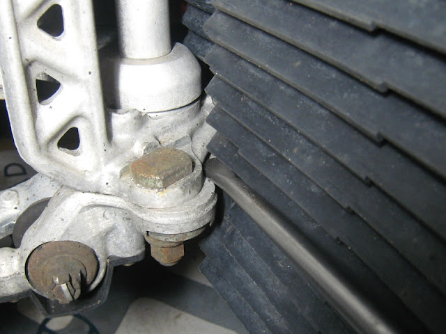
The aim is to create a tiny gap between the lower mount/arm and
the cup where the corrosion has occurred.
Then you can apply the penetrating oil through the gap (probabaly
less than 1mm) and hope it will free up the cup.

The corrosion inside the cup.
Even with such small amount, its enough to
seize the adjuster because of the tight fit of
the cup around the lower mount/arm.
If you are going to remove the pivot off the car,
then try to remove the corrosion and apply thin
coat of silicone grease to prevent future
corrosion.
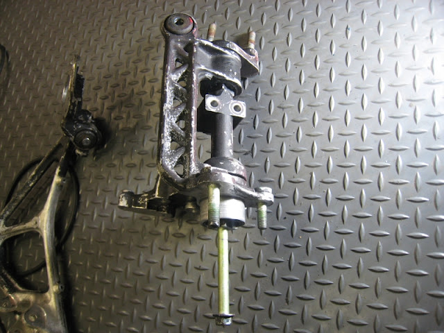
The structure.
The upper and lower mounts are inserted into the
sophisticated bush at the top and bottom section
of the arm.
In the above photos, you can see the star/square like
piece that is part of the upper mount through the upper bush.
And the same shape at the lower mount inserted
through the lower bush.
The T-piece is where you normally install the
pivot cancellor.
Although it's a tight fit between the bush and the lower/upper
mount, the bush can slide around the mounts so the position of
the arm will be decided by the rest of the suspension arms/parts.
This is the reason why you sometimes see small gap between the
base of the two mounts against the arm but because of the high
accuracy of the NSX parts and assenbly process, normally you
won't see any gaps.
You want to slide the cup off the lower mount/arm
a little to break the corrosion and create tiny gap
allowing the penetrating oil to flow through.
While the pivot is still on the car, all of the ball joints are
still connected to the pivot so you will be able to
create only a tiny gap, probably less than 1mm.
Above photos show the cup being separated from
the lower mount/arm purely to describe how it is fitted
and obviously, you won't be able to achieve this
while the ball joints are still connected.
While the pivot is on the car, you need to remove the
slotted A/C condenser fan black plastic cover inside
the wheel arch.
Then at the front lower section of the arm,
you will find nice recess where you can insert
the pry bar.
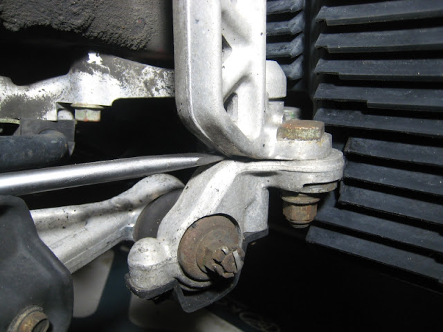
On the other hand, at the opposite side of the lower mount/arm
where you want to insert another pry bar,
you may not have ideal condition to apply enough leverage.
In this photo, I placed the tool from this angle just to show
where you want to apply the leverage but in real world,
you will need to insert the tool from behind the arm, i.e. from the
direction where your spare wheel is located.
Because of this, you need angled pry bar otherwise
the sway bar, frame panel, etc will obstruct any leverage action.
Also, depending on the existing caster setup, you may not have
ideal condition/geometry to place your angled pry bar at
the indicated position (between the bottom of the arm and the cup).
As a side note, please do not use high heat on aluminium parts.
I don't know the exact alloy composition (#5000, #6000, etc) used
on the pivot but it may permanently change the charaterristic of the
alloy structure resulting in long term cumulative fatigue fracture.
Good luck.
Kaz


Tags:
caster,
compliance pivot,
serized caster

- Categories
- Suspension
 Email Blog Entry


